Monday, November 5, 2007

Fuel Cell and Front Uprights

The welder we had lined up for the fuel cell never got around to welding the tank so we picked it up and started practicing welding aluminum. We quickly found out that our archaic Miller welder was not up to par to create beautiful aluminum welds. But I can still show you the internal surge tank and low pressure pump.

Here is the inside of the mocked up fuel cell. You can see the low pressure fuel pump in the right side of the picture and the aluminum tube that directs the fuel into the surge tank. You can see the flange for the fuel pump in the bottom of the surge tank.

Also the front uprights have made some impressive progress. Here you can see them fully tacked together. They are lighter then the previous years aluminum uprights. This just goes to show that a little bit of thought can make fabricating out of steel a very good option.


Posted by Picasa

Wiring

One are that teams really struggle with is the wiring harness. So we paid special attention to create a well throughout and executed harness. We tried to create a harness that looks professional, something that looks better then you would find in your own cars. For this we used a high temp braided sleeve that the wires were covered with. To secure the sleeve we used a combination of self vulcanizing tape and adhesive lined shrink tubing. Here are the results.


One feature that is unique is the use of a bulkhead connector. This connector acts as a through connector into the electronics box eliminating the possibility of wires chafing on the edges of a grommeted hole. It also make engine removal very simple. To disconnect the wiring system you disconnect the bulkhead connector, starter and alternator, and as far as the wiring goes... your done.

Where the harness split into different areas we would use shrink tubing. On one side it would be a single large bundle, on the other it would split into multiple harnesses. To take this harness one step further you could use pre-molded harness "T"s and "Y"s. Also before covering the wire with the braided sleeve you could cover the bundled wires with heat shrink. This would give the harness a nice black look and really seal out all of the elements. However, what we have achieved here is far superior to previous years and the majority of the cars I've seen at the competition.
Posted by Picasa

Intake System

Josh Nell really did a great job in designing and building the intake system for the car. The design retains some of the important components from the stock system such as the fuel rails, injectors and intake trumpets.

Here is the front of the intake you can see the air filter which might be replaced with one slightly larger later on but its filter area is larger then the throttle bodies cross sectional area.

Here is a picture showing the secondary fuel rail. Note the nice cut out around where the fuel line needs to go.

Here you can see the stock trumpets that we are utilizing. The different heights are tuned to different RPMs, the effect is they will increase the usable RPM range. You could achieve higher peak hp if you used one set height but usable power is more important then peak power.

Here you can see the intake air temperature sensor nestled in with the injectors. It is positioned so it will not be in the spray of the fuel injectors, as this would cause erratic air temps whenever the secondary fuel rail is activated.
Posted by Picasa

Engine Tuning

Once we got the engine to run last time we needed a slightly more permenent solution for the fuel delivery and we also needed to figure out how to keep the engine cool durring our tests.


For cooling we instaled a electric water pump. A really nice unit that uses a brushless motor that is sealed in a plastic housing. this motor drives an impeller through a magnetic coupling. Pretty inginous. For the sake of simplisity we used a thermal resivor instead of a radiator and fan. This way we could easily keep the engine in a safe temprature zone. The thermal resivor consists of a large cooler filled with water. The electric water pump continously cerculates the water through the engine. When the water gets to hot we just refill it with cool water.

Josh N. is replacing the intake system.

Here is the engine in one of its first runs. The muffler that we are using is from a RM250F and works quite well. The smoke is from oil that was sitting in the headers. The headers that we are using came of a bike that had blown up... Remember our first engine.


Posted by Picasa

Engine tuning.

After finishing the bulk of the chassis we got the engine, electronics, intake system and exhaust system fitted so we could start doing some engine tuning.

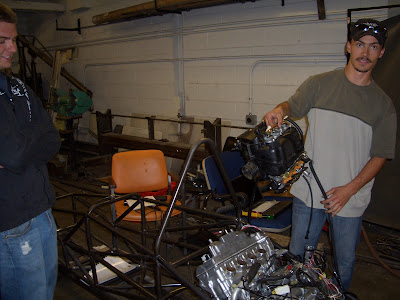
From left to right we have Brett, Josh N. and Eric helping get everything sorted.

Because we are still waiting, now less patiently, for our fuel cell to be welded we needed a fuel source. Ben came up with the simple idea of hooking up to his 300Z fuel system with a long piece of fuel tubing.

After awhile of trouble shooting wiring...
"Hey, do you smell something burning?"
"Yeah, smells like electronics."

We frantically disconnect the battery and pray that the distinct smell of fried electronics was not our MoTeC M4 ECU. After some searching I found that one of our coil-on-plugs had given up the good fight. Lesson learned... if you are not running the engine the coils will burn up.

Pretty spectacular destruction. The laminated metal core was fractured, impressive amount of heat. We replaced the coil and proceeded with more caution.
Posted by Picasa

Pedals

After working on the chassis for about 2 weeks straight now we needed a little change of pace. So we set out to build the pedals for the car. The design work was all done in SolidWorks and some pretty slick stamped steel pedals were the result. The main reason for the development of the pedals is to achive the correct pedal ratio so that the brakes "feel" right. Normal pedal ratios would give the driver a very soft pedal and large pedal travel, undesirable features in a racecar.

Here is the clutch pedal all welded up, yes our car will have a clutch pedal. I can hear teams around the nation gasping as I type. As this car is designed for the non professional driver we felt that the familiar control layout far out weighed the performance benefits from having a narrow chassis.

Here is a close up of the welded brake pedal. The upper half of the photo you can see the Willwood balance bar assembly that has been integrated into our pedal. in the bottom right corner you can see the pivot point, note the teflon bushing.

Here are the finished pedals. Grip tape was applied to the pedal surfaces to increase the drivers confidence.

Here you can see the back side of the clutch pedal with the adjustable travel stop at the bottom. The throttle pedal is a mirror image of the clutch pedal.
Posted by Picasa

Engine Mounts Completed

The rotisserie that the chassis is on really help the welding process. Here we are finishing the motor mount welds and doing some high g testing. We know that the motor mounts are solid to -1 vertical g. Hopefully the last time that the chassis will ever be in this position.


Brett finishing the motor mount welds.


Motor fitted.

Brett testing for driver comfort and taking a much needed break.
Posted by Picasa